
Common op amp application circuits include non-inverting proportional amplifiers, voltage followers, inverting proportional operational amplifiers, adders, subtractors, integrators, etc. The characteristics of the operational amplifier are that the input impedance tends to infinity, and the output impedance approaches zero. When working in the linear region, the non-linear region can be applied to the voltage comparator by using the virtual break and virtual short analysis circuits.
Definition of Operational Amplifier
An operational amplifier refers to a circuit that can perform mathematical operations and has an amplification function to amplify the input signal. The operational amplifier can be referred to as OPA for short, and the circuit symbol is as follows:
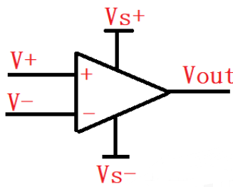
Op Amp Circuit Symbol
Understanding of Virtual Break and Virtual Short in Operational Amplifiers
The premise of the introduction of virtual short and virtual break is that the operational amplifier works in the linear region. Virtual short refers to the fact that the non-inverting input terminal and the inverting input terminal are equivalent to being short together, and the voltages are equal at this time. The input impedance of the operational amplifier is extremely large, and the current reaches the uA level, which is similar to an open circuit and is called a virtual break. In the following circuit, it is mainly analyzed from virtual short and virtual break.
In-phase proportional operational amplifier
Virtual short: V+=V-
Virtual break I-=0
V-=V+=(R1*(R1+R2))*VOUT
Namely: VOUT=V+*(1+(R1/R2))

voltage follower
From the same-phase proportional amplifier VOUT=V+(1+(R1/R2)), when R2 approaches infinity, the output and input are the same size, which is called a voltage follower.

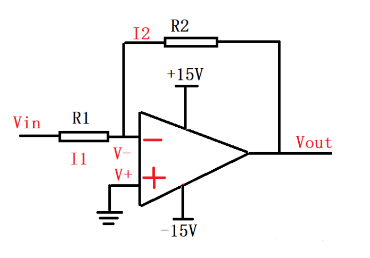
Inverting Proportional Operational Amplifier
Virtual short: V+=V-=0
Virtual break I-=0=I+
VIN/R1=-VOUT/R2
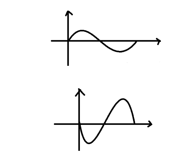
That is: VOUT=-VIN(R2/R1), here it should be noted that the GND terminal of the op amp power supply should be connected to the positive power supply.
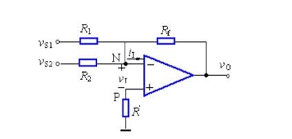
adder
Virtual short: V+=V-;
Virtual break: V+=0; that is, V+=V-=0’
The current flowing into the node is equal to the current flowing out of the node as follows:
(VS1-0)R1+(VS2-0)R2=(0-UO)/RF; when the three resistors are equal, R1+R2=-UO; the symbol in front of UO can be reversed by placing a first stage after the adder The phaser can realize addition.
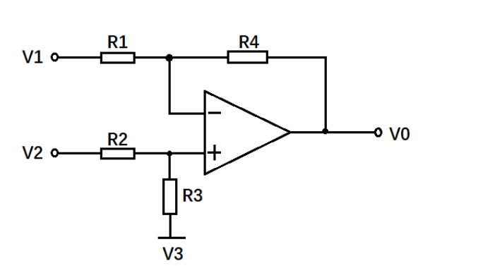
Subtractor
Short circuit: V+=V- (V2-V3)(R3/(R2+R3))=(V1-VO)(R1/(R1+R4))
When R1=R4, R2=R3, (V2-V3)/2=(V1-VO)/2 can get V1-V2=V0, which is derived from the subtractor formula.
Integrator circuit
The integral circuit can realize the integral operation of different input signals, so as to realize the transformation of the waveform, and the square wave can be turned into a triangular wave after the integral operation. The derivation is as follows:
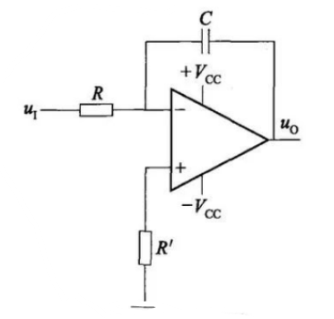
According to the law of energy conservation, the output current is equal to the input current, and the current through R is equal to the current of the capacitor. It can be deduced that VO=(-(R1*C1))∫V1dt is obtained by integrating the input voltage within a certain period of time to obtain the output voltage.


