
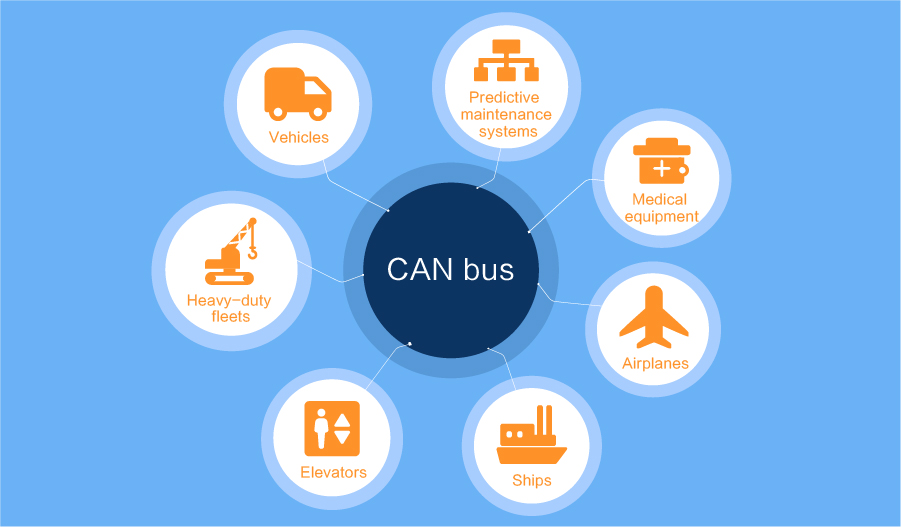
Overview of CAN Bus
The CAN bus was developed by BOSCH, a German company famous for R&D and production of automotive electronic products, and eventually became an international standard (ISO11519). It is one of the most widely used field buses in the world. The CAN bus is a multi-master bus system.
Traditional bus systems such as USB or Ethernet realize the transmission of large amounts of data from node A to node B under the coordination of a bus controller. The messages of the CAN network are broadcast, that is, the data detected by all nodes on the network at the same time is consistent. It is a serial communication bus based on the message broadcast mode.
Get to this page quickly
There are 4 common topology types of CAN bus, namely: linear topology, star topology, tree topology, and ring topology. Because the distribution line of the CAN bus is affected by factors such as environment and products, the phenomenon of too long/too many branches of the bus appears in field wiring. When the system bus is too long, the line is too long. This will lead to sudden changes in impedance, or impedance discontinuity, and there will be rising and falling edge steps, which can easily lead to erroneous identification during logic identification. This results in bit width misalignment and nodes receiving incorrect information.
"As a China CAN2.0 Communication Modules supplier and Factory, CDEBYTE focuses on providing wholesale CAN converter online. CAN series cover dual channel CAN to WIFI Converter, CAN to RS485/RS232/RS422 converter, CAN to optical fiber converter, and CAN to USB converter.ECAN
series is a small intelligent protocol conversion product independently
developed by CDEBYTE. The product supports serial AT command
configuration and host computer configuration device parameters and
working modes and supports five data conversion modes including
transparent conversion, transparent conversion with logo, protocol
conversion, Modbus RTU conversion, and user-defined (user). At the same
time, ECAN intelligent protocol converter has the characteristics of
small size and easy installation"
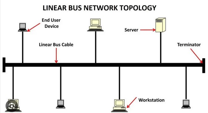
Linear bus topology is the simplest structure in the CAN bus. In this topology, all CAN nodes are connected to one main bus, and each node communicates over the bus. This topology type is suitable for small to medium-sized networks where the number of nodes is limited. Its main features are low cost and easy maintenance. However, linear topologies can result in increased communication latency because nodes must wait for other nodes on the bus to complete communication.
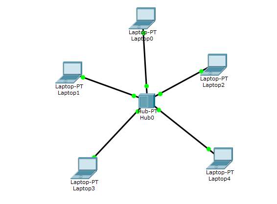
Star bus topology connects all CAN nodes to a central hub or switch. Each node is connected to a hub and not directly to other nodes. This topology provides better network management and isolation because each node can connect and disconnect independently without disturbing the entire network. It is often used in large CAN networks to reduce communication delays in linear topologies.
Tree bus topology is a hybrid structure that combines linear topology and star topology. It allows the creation of multiple subnetworks, each of which can have its own linear or star topology, and then connecting them together through one or more hubs. This topology is suitable for large and complex CAN networks, and it provides greater flexibility to implement different types of communication between different parts.
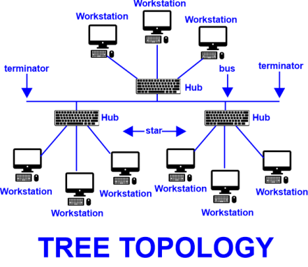
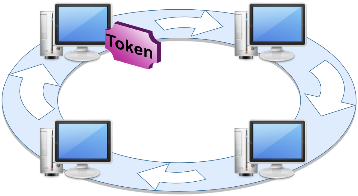
Ring bus topology is a combination of different topologies to meet specific network needs. This topology can include a combination of linear, star, tree, or other structures to better meet communication needs. The advantage of a hybrid bus architecture is that it can be customized based on actual needs to provide optimal performance and reliability.
It is clearly stipulated in IOS11898-2 that under the condition of 1M baud rate, the maximum CAN branch length is 0.3 meters at 1Mbps. So we should develop specifications for the longest branch distance based on different baud rates. In principle: the sum of branch lengths + trunk length < bus transmission limit length (limit length * 0.7) is used. The sum of branches generally does not exceed 30% of the total length.
CAN bus hardware requirements:
CAN bus systems require specific hardware components to ensure that nodes can transmit and receive data on the bus. The following are the key aspects of CAN bus hardware requirements:
CAN controller chip: Each CAN node requires a CAN controller chip to handle the sending and receiving of data frames. This chip usually integrates the core functions of the CAN protocol, including frame assembly and parsing, error detection and retransmission, etc.
Physical layer converter: The physical layer characteristics of the CAN bus usually involve changes in voltage levels, so a physical layer converter is needed to ensure that the signal adapts to the electrical characteristics of the bus. These converters are usually differential signal converters, used to convert the single-ended signal of the node to the differential signal of the CAN bus.
Terminal resistor: Terminal resistors are usually required at both ends of the CAN bus to eliminate signal reflection and ensure the correct transmission of the signal. These terminating resistors are connected to both ends of the bus and are typically 120 ohms.
Proper power supply: CAN nodes require proper power supply for their operation. This includes voltage and current requirements to ensure the node is functioning properly.
Appropriate connectors and cables: In order to connect the nodes to the CAN bus, appropriate connectors and cables are required. These should be able to physically connect the nodes and provide a reliable electrical connection.
For large CAN bus networks, effective network management is crucial to ensure network stability and reliability. The following are some key aspects related to CAN bus network management:
Node allocation and address management: In the CAN bus network, each node needs to be assigned a unique address. Network administrators are responsible for assigning and managing these addresses to ensure there are no conflicts and confusion.
Communication speed and bandwidth management: Communication speed and bandwidth need to be managed according to the needs of the network. This includes selecting the appropriate CAN bus speed to meet data transfer requirements.
Fault Detection and Troubleshooting: Network management also involves detecting and troubleshooting faults. This includes monitoring the status of nodes, detecting error frames, and taking action to deal with failed nodes.
Security management: With the increasing application of CAN bus in automobiles and other fields, security management has become particularly important. Network administrators need to take steps to ensure that the network is not vulnerable to malicious attacks or unauthorized access.
Performance Optimization: For optimal performance, network management can involve adjusting network parameters such as communication speed, message priority, and message filtering.
How to solve the problem of CAN bus being too long
(1) Reduce branch length
To solve the problem of too long CAN bus from the root, it is to reduce the branch length of CAN nodes, thereby reducing signal reflection and ensuring the stability of the bit width. The standard "hand-in-hand" interface wiring standard method can be used to minimize the length of the branches to reduce the branch length problem.
(2) Add appropriate resistors to long branches
When we cannot change the network layout, signal reflection caused by too many branches is bound to exist. The simplest and most practical method is to string resistors at the ends of long branches to eliminate signal reflections. However, the differential voltage will decrease after adding a resistor. Note that the differential voltage here must not be less than 0.9V.
(3) Add CAN relay or hub
In many situations, when we can no longer change the branch length and connect series resistors in the branches, we can use CANBridge relays or CANHub hubs. Networking equipment such as CANHub hubs are branched. Each channel of these devices has an independent CAN controller, so each section can be formed into an independent linear topology to facilitate construction.


