
A Network Interface Card (NIC for short), also known as a network adapter, is a device that connects a computer to a local area network. As long as it is connected to a LAN, a network card needs to be installed. A network card mainly includes the bottom two layers of OSI, the physical layer and the data link layer. The chip of the physical layer is called the PHY, and the chip of the data link layer is called the MAC controller. over the introduction.
Today we come to understand the working principle of the network card and learn the process of sending and receiving data packets.
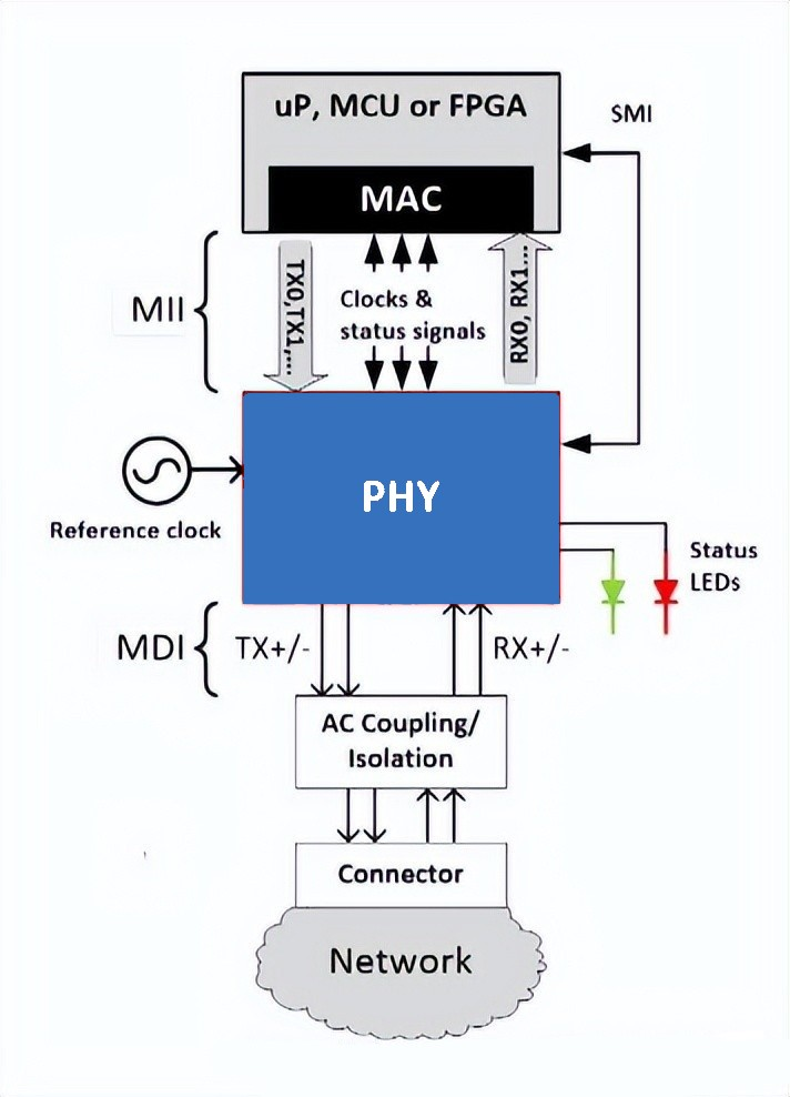
The network card works in the last two layers of OSI: the physical layer and the data link layer. The physical layer defines the electrical and optical signals, line status, clock reference, data encoding and circuits required for data transmission and reception, and communicates to the data link Layer devices provide standard interfaces. The data link layer provides functions such as addressing mechanism, data frame construction, data error checking, transmission control, and standard data interface to the network layer. The chip of the data link layer in the Ethernet card is called the MAC controller. These two parts of many network cards are done together. The relationship between them is that the PCI bus is connected to the MAC bus, the MAC is connected to the PHY, and the PHY is connected to the network cable (through the transformer).

Let's continue to look at how PHY and MAC transmit data and communicate with each other. Connect MAC and PHY through the standard MII interface defined by IEEE. This interface is defined by IEEE. The MII interface transfers all data and data control of the network. The MAC determines the working state of the PHY and controls the PHY by using the SMI (Serial Management Interface) interface by reading and writing the registers of the PHY. Part of the registers in the PHY are also defined by IEEE, so that the PHY reflects its current status into the registers, and the MAC continuously reads the status register of the PHY through the SMI bus to know the current status of the PHY, such as connection speed and duplex capability Wait. Of course, you can also set the PHY registers through SMI to achieve control purposes, such as opening and closing flow control, auto-negotiation mode or mandatory mode, etc.
Therefore, whether it is the physically connected MII interface and SMI bus or the status register and control register of the PHY, there are IEEE specifications, so MACs and PHYs of different companies can work in harmony. Of course, in order to cooperate with some unique functions of PHYs of different companies, the driver needs to be modified accordingly.
work process
When the PHY sends data, it receives the data from the MAC (for the PHY, there is no concept of a frame, for it, it is all data regardless of the address, the data is still CRC), and every 4 bits add 1 bit of error detection Code, and then convert the parallel data into serial stream data, and then according to the coding rules of the physical layer (NRZ coding of 10Based-T or Manchester coding of 100based-T), the data coding is converted into an analog signal and sent out. The process of receiving data is reversed.
Now let's look at the latter part of the output of the PHY.
When a CMOS process chip is working, the signal level generated is always greater than 0V (this depends on the process and design requirements of the chip), but such a signal will have a large DC voltage when it is sent 100 meters or even farther away. weight loss. Moreover, if the external network cable is directly connected to the chip, electromagnetic induction and static electricity can easily cause damage to the chip.
Furthermore, the grounding method of the equipment is different, and the different grid environment will cause the 0V levels of the two parties to be inconsistent. In this way, the signal is transmitted from A to B. Since the 0V level of A equipment is different from the 0V level of B point, this will cause a large current. Flow from a device with a higher potential to a device with a lower potential. At this time, Transformer (isolation transformer) is needed. It filters the differential signal sent by the PHY with a differential-mode coupled coil coupling filter to enhance the signal, and couples it to the other end of the network cable through the conversion of the electromagnetic field. In this way, there is no physical connection between the network cable and the PHY and the signal is transferred, the DC component in the signal is cut off, and data can also be transmitted in devices with different 0V levels.
The isolation transformer itself is designed to withstand the voltage of 2KV~3KV, and at the same time it plays the role of lightning protection. Some users' network equipment is easy to be burned out in thunderstorm weather, most of which are caused by unreasonable PCB design, and most of them burnt the interface of the equipment, and few chips are burned, because the isolation transformer plays a protective role.
When sending data, the network card first listens to whether there is a carrier on the medium (the carrier is indicated by the voltage), and if there is, it thinks that other stations are transmitting information and continues to listen to the medium. Once the communication medium is quiet for a certain period of time (called the inter-frame gap IFG=9.6 microseconds), that is, it is not occupied by other stations, frame data transmission is started while continuing to listen to the communication medium to detect collisions. During the transmission of data, if a collision is detected, the transmission is stopped immediately, and a "block" signal is sent to the medium to inform other stations that a collision has occurred, thus discarding the corrupted frame data that may have been received, and waiting A random amount of time (CSMA/CD's algorithm for determining the waiting time is a binary exponential backoff algorithm). Wait for a random amount of time before making a new send. If a collision still occurs after multiple retransmissions (greater than 16 times), the transmission is abandoned.
When receiving, the network card scans each frame transmitted on the medium, and if it is less than 64 bytes in length, it is considered a collision fragment. If the received frame is not a conflicting fragment and the destination address is a local address, check the integrity of the frame, if the frame length is greater than 1518 bytes (called an oversized frame, it may be caused by a wrong LAN driver or interference) or If it fails to pass the CRC check, it is considered that the frame is distorted. Frames that pass the verification are considered valid, and the network card receives them for local processing.


