
1. Introduction to the system
With the development and application of IoT technology, many emerging IoT platforms and protocols have emerged. LoRaWAN is a LoRa-based star network that uses LoRa's low power consumption and long distance characteristics. This network is suitable for various meter reading services. The LoRaWAN network consists of three main parts, the device side, the gateway and the server side.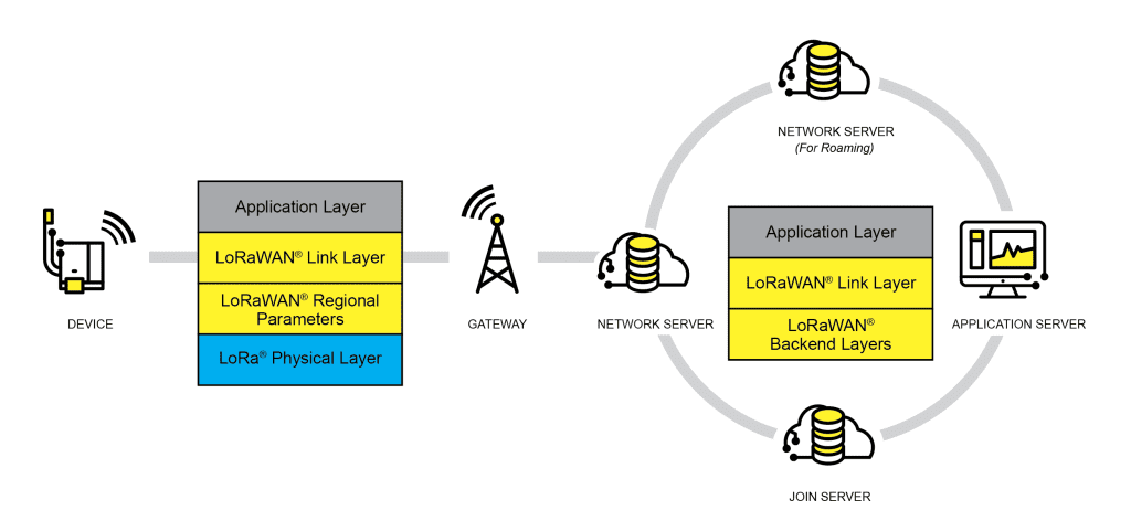
The following is the use of E78-DTU, E890-470LG11 LoRaWAN gateway to build a LoRaWAN automatic acquisition system. The LoRaWAN server adopts ChirpStack open source server. The schematic diagram of the whole system is as follows. The equipment side uses E78-DTU to connect with the collected equipment through RS485, E78-DTU communicates with the E890-470LG11 gateway through LoRa, the gateway forwards the data to the cloud server through the network, and the cloud server makes corresponding processing and forwards it to the client.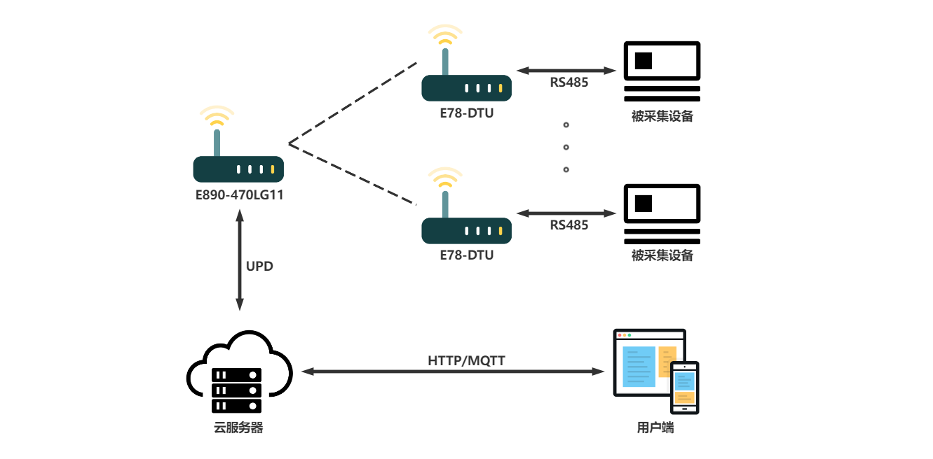
2. Build the environment
1. Brief description of Chirpstack server construction process
Chirpstack is an open source LoRaWAN server, which is simple to build, occupies less server resources, and supports many API interfaces.
For the construction process, please refer to the official website, Chirpstack official website address: https://www.chirpstack.io/
Quick deployment projects can be used here. The Github repository address is as follows:
https://github.com/brocaar/chirpstack-docker
After the configuration is complete, log in to the configuration website. The default account password is admin.
2. E890-470LG11 configuration process
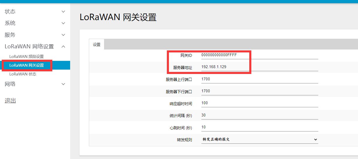
Turn on the E890-470LG11 and use the laptop to connect to the WiFi of the gateway, named EBT-E890-XXXX. Enter 192.168.10.1 in the browser to enter the configuration page, and the password is root. The gateway ID matches the configured ID on the server, and the IP address is modified to the server's IP address. After the configuration is correct, the LINK light of the gateway will be always on to indicate that it is now connected to the server.
3. E78-DTU configuration process
E78-DTU uses the matching configuration host computer configuration. Select the corresponding serial port, open the serial port and click to enter the configuration, the server produces AppEUI and AppKEY, fill in 0 for APPEUI, then click Write Parameters to write the parameters to the device, and finally click to exit the configuration, if the configuration is correct, the device LINK light will always be on.
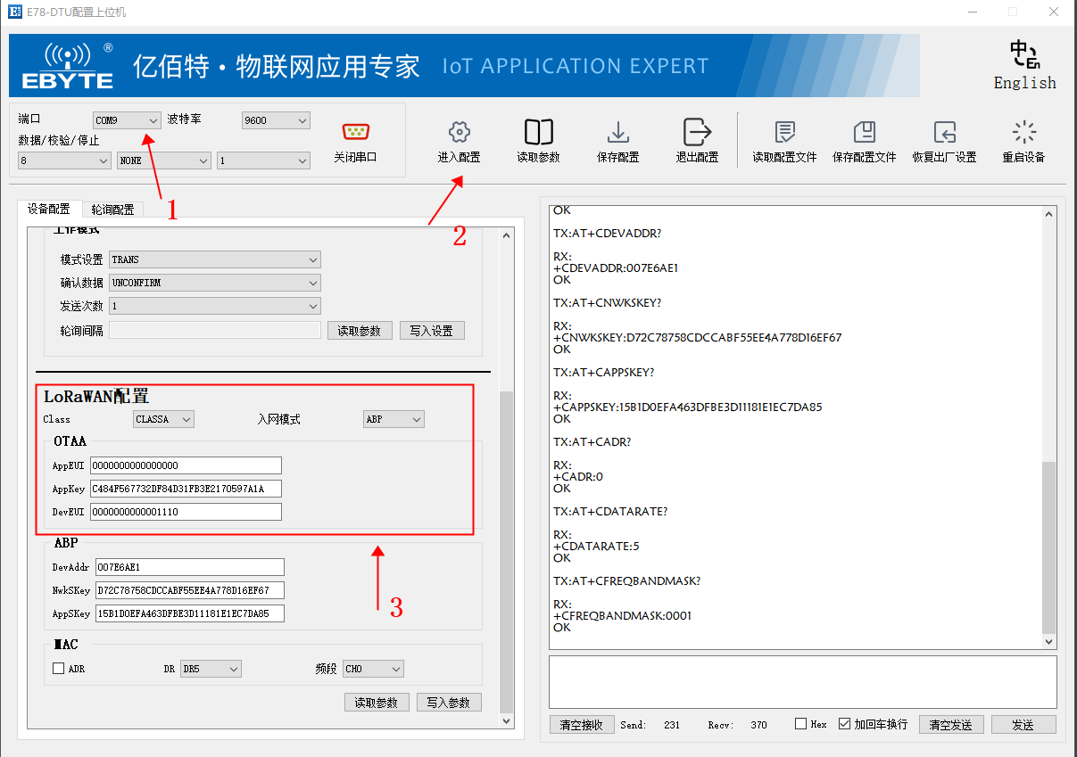
Configure the automatic polling parameters, and enter the corresponding command according to the polling data, the timeout time of the collected device, the collection interval and whether to add CRC check. The figure below is configured as a polling Modbus command, and the read coil, read discrete input register, read holding register, and read input register are added in sequence in the figure below. After adding two bytes of CRC-16 (Modbus) check.
At the same time, the DTU is set to the polling mode as shown in the figure below, and the interval between two large polling events can be set according to actual needs.
4. Client configuration
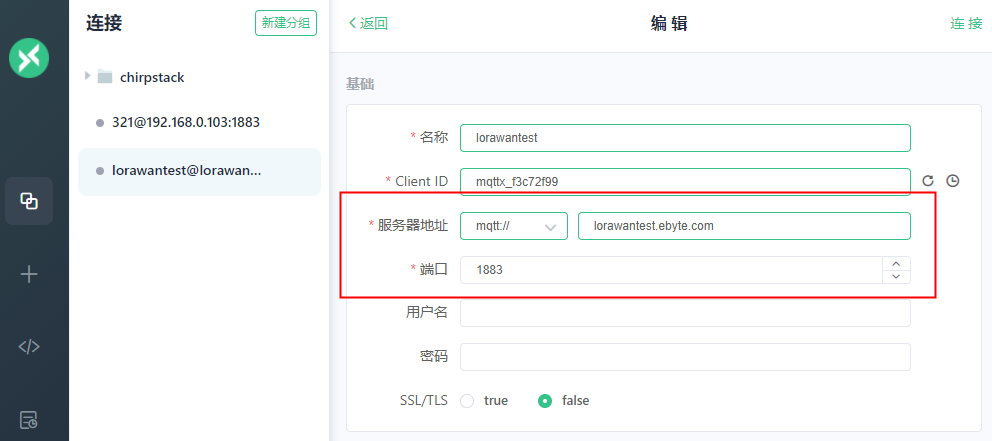
Here, use the MQTTX software to subscribe to the upstream data topic of the Chirpstack server, first connect to the Mqtt server, and enter the correct server address and port.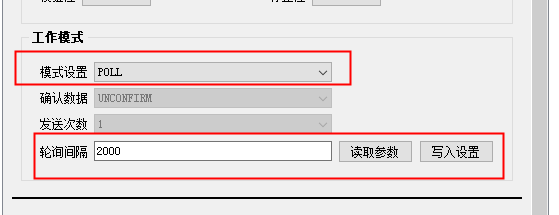
Enter the subscription topic format according to the information configured on the server as follows:
application/application ID/device/device DevEUI/event/up
After the configuration is normal, the data forwarded by the server can be received normally
The original data is obtained by BASE64 decoding the data data in the forwarded data, and the fPort of each packet of data corresponds to the serial number of the polling instruction. The decoded data is the data returned by the acquisition device.
Serial number (fPort) Original data Decoded data
1 AQEBAFGI 01 01 01 00 51 88
2 AQIBAWBI 01 02 01 01 60 48
3 AQMEAAD9F/qt 01 03 04 00 00 FD 17 FA AD
4 AQQERFFZEUT5 01 04 04 44 51 59 11 44 F9
The automatic acquisition system built with Chirpstack, E890-470LG11 and E78-DTU can quickly build an IoT network, simplifying the process of building end-to-cloud, while using LoRa radio frequency technology to improve the communication distance, improve the communication distance of equipment, and automatically collect data It can simplify the collection process and save labor costs. Networks built with Chirpstack servers can reduce device management.


