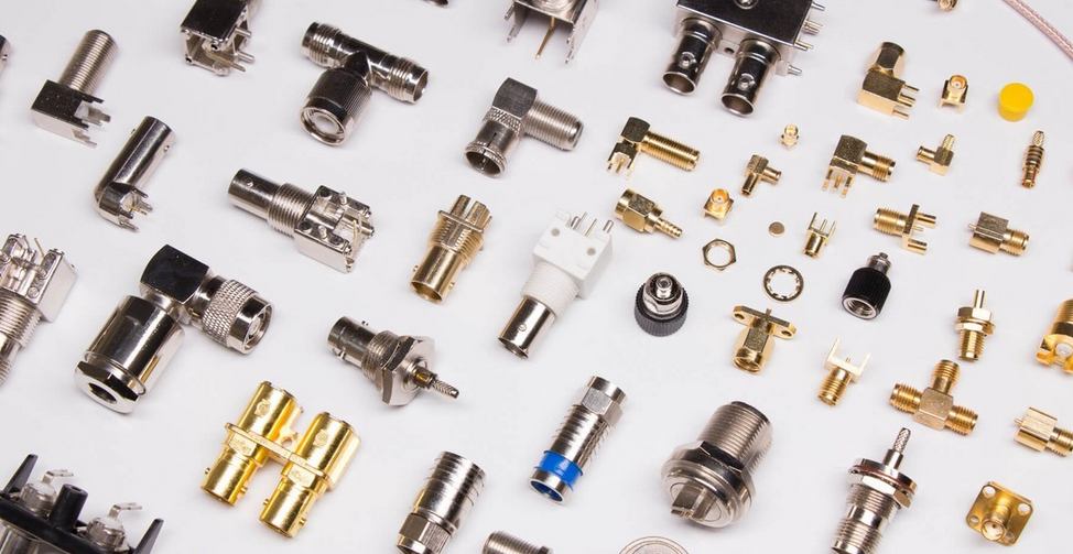

A radio frequency connector is a radio frequency coaxial connector, which is usually regarded as a component attached to a cable or installed on an instrument as a component for electrical connection or separation of transmission lines. The function of the radio frequency connector is to connect or disconnect two radio frequency ports when needed, so as to realize the electrical connection, separation or transfer of different types of transmission lines.
Main Specifications of RF Connectors
Impedance: Almost all RF connectors and cables are standardized to an impedance of 50Ω. An impedance system of 75Ω is commonly used in cable TV installations. RF coaxial cable connectors have a characteristic impedance that matches the cable. Whether the impedance is matched is directly related to the quality of signal transmission.
Connector size: For RF signals of the same frequency, a connector with a larger size has a higher power tolerance. Among the commonly used RF coaxial connectors, 7/16 (DIN), 4.3-10, and N-type connectors are relatively large in size, and the corresponding pinhole size is also large. Generally, the power tolerance of N-type connectors is about 3 times that of SMA. -4 times. Most passive components such as attenuators and loads above 200W are N-type connectors, while low-power and small-volume wireless modules are connected by SMA, and smaller-sized ones such as mobile phones, Bluetooth modules, etc. will use smaller volumes. IPEX interface, the figure below shows N-type RF connector, SMA interface, and IPX interface from left to right.
VSWR (Voltage Standing Wave Ratio): Voltage standing wave ratio refers to the ratio of the antinode voltage of the standing wave to the amplitude of the node voltage, also known as the standing wave coefficient and the standing wave ratio. When the VSWR is equal to 1, it means that the impedance of the feeder and the antenna are completely matched. At this time, all the high-frequency energy is radiated by the antenna, and there is no reflection loss of energy; when the VSWR is infinite, it means total reflection and no energy is radiated at all. For RF connectors, the lower the standing wave ratio, the better.
Frequency range: The power tolerance of the RF coaxial connector will decrease as the signal frequency increases. The change of the transmission signal frequency directly leads to the change of the loss and the voltage standing wave ratio, which affects the transmission power capacity and the skin effect. For example, a general SMA connector can withstand about 500W of power at 2GHz, and can withstand less than 100W of average power at 18GHz. For passive components such as attenuators and loads with frequencies higher than 18GHz, the average power withstand is mostly within 100W.

Insertion loss: refers to the loss of power on the line due to the introduction of RF connectors. Defined as the ratio of output power to input power, there are many factors that increase the insertion loss of the connector, mainly including: mismatch of characteristic impedance, assembly accuracy error, mating end face clearance, axis inclination, lateral offset, eccentricity, machining accuracy and caused by electroplating, etc. Due to the existence of loss, there is a difference between the input and output power, which also affects the signal transmission effect.
Runtime: How many connections/disconnects it can withstand and still meet its specifications. This is usually at 500 or 1000 cycles. For threaded connectors, the tightening torque specified by the supplier is one of the important factors in maintaining its performance and reliability.
Power: In general, the power tolerance of a connector decreases as the signal frequency increases. For the RF signal of the same frequency, the power of the connector with a large size is large. For example, a general SMA connector can withstand about 500W of power at 2GHz, and less than 100W of power at 18GHz. BMA is about the same as SMA, and the power tolerance of N-connector is about 3-4 times that of SMA. If the matching of the transmission process is not good and the standing wave is too large, the power on the connector may be greater than the incident power. Generally, for safety reasons, the power loaded on the joint should not exceed 1/2 of its limit power. Today's designs focus on low-power devices such as cell phones, cellular and mmWave base stations, and video interfaces. These are in the 1W range, so the connector can be much smaller and its power rating is smaller.
Contact resistance: The contact resistance of a radio frequency connector refers to the resistance of the contact points of the inner and outer conductors when the connector is inserted. Generally, it is at the Bo ohm level, and the value should be as small as possible. It mainly evaluates the mechanical properties of the contact parts. The influence of solder joint resistance, the existence of contact resistance will cause the contact to heat up, making it difficult to transmit high-power microwave signals.
Selection of RF Connectors
1. The selected RF connector should conform to the actual frequency range used.
2. The selected RF connector should have a smaller standing wave ratio.
3. When there are IM requirements, the material and plating of the RF connector should be considered.
4. The selected RF connector should match the impedance of the mated RF connector or cable.
5. The EMC of threaded RF connectors is better than any bayonet, push-pull RF connectors.
6. The selected RF connector should have a small insertion loss.
7. Under normal circumstances, the electrical performance of straight RF connectors is better than that of curved connectors, which can be selected according to the actual use.
We are a professional manufacturer and supplier of RF products such as E32-900M20S
, browse our company homepage to find more details and download information 。
- Why RFID can be called the perfect passive IoT technology
- 【SPI】SX1278,LoRa,long distance, anti-interference
- 【nRF52840】BLE SoC Module
- Five reasons to choose Bluetooth module instead of RFID for asset location management
- Application of RFID Technology in Intelligent Logistics
- E78-900M22S is a SoC LoRa RF module designed by Ebyte with max transmitting power of 22dBm


